OSCAR WONG
POP'N MUSIC CONTROLLER BUILD
This was a personal project in which I build a replica of the controller for the arcade game Pop’n Music on a college budget.
The first part of this project was getting the buttons. Official buttons by Sanwa are available for sale, but are far outside of my price range at over 40 dollars each, so I ordered some identically dimensioned buttons from China off eBay and waited for them to arrive a few weeks later. These came with LEDs and microswitches, which would allow me to detect button presses.
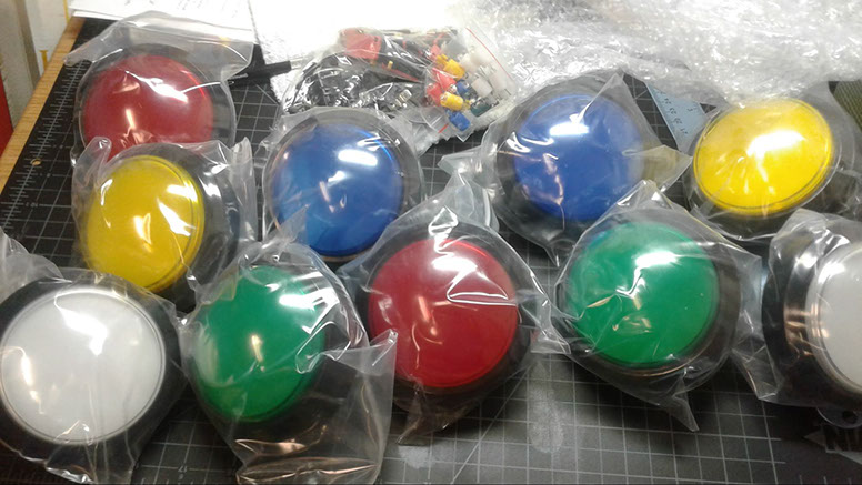
The buttons, microswitches, and LEDs, fresh out of the box.
Total cost so far: $75.26
The next part was buying the wires and other electronic components necessary to interface these buttons with my computer. Since I do not own a soldering iron, I decided to use quick-connect crimp terminals, which would create solid connections to the switches and allow me to swap out components for future repair. I already had a spare Arduino and USB cable sitting around, which I would wire the buttons to. A quick trip to the ECE Supply Center provided me with a spool of 22ga solid core wire, crimp connectors in two different sizes (for the microswitch and LED terminals), and some rubber feet, which would hold the entire controller steady.
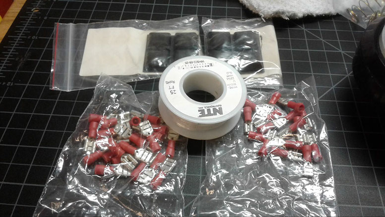
Parts from the ECE Supply Center.
Cost of parts: $10.51
Total cost so far: $85.77
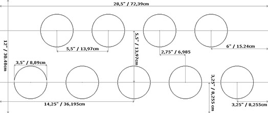
Next, I needed to mount the buttons to a faceplate of some sort (these are typically made out of MDF, acrylic, sheet metal, etc) before I could wire them up. I was conveniently provided with these dimensions of the buttons from the eBay listing, as well as this diagram of the button spacings for the actual controller online.
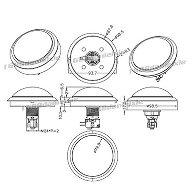
Button dimensions, showing additional mounting nubs.
Button spacing diagram.
1 - 2
<
>
The easiest way to create arbitrary, well dimensioned cuts on a flat sheet of non-reflective material is a laser cutter, which the school has available at the Fab Lab. They take PDF files, and will vector cut any lines with a thickness of .001 inches. With this in mind, I created a PDF file in Illustrator that would cut out holes with the given dimensions spaced correctly apart. One requirement was that the controller would have to fit into a space no larger than 24” - the length of the largest luggage I have. Unfortunately, since the proper dimensions of the controller exceed 28”, I designed it to be laser cut on two sheets, each made of three parts. This would assemble together into a single solid unit, and could later be disassembled into 6 separate parts, with the longest at 22”.
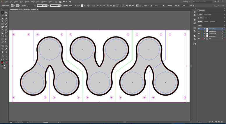
An overview of the entire controller.
In this overview of the entire Illustrator file, the green lines are vector cuts on the top sheet, the dark blue lines are vector cuts on the bottom sheet, and the dark grey and black lines are to be rastered on the top sheet, simulating the arcade artwork. Red lines are vector cuts on both sheets for nuts and bolts to hold the whole thing together.
The next step was actually getting massive sheets of acrylic. Unfortunately, since 12x30” is not a standard size, I had to head to the next largest size - a massive 18x32”, which was one and a half times the acrylic I needed. I picked two sheets up at Blackline Supply, one black and one clear, so that the engraved design on the clear layer would pop out in contrast.
Cost of acrylic: $47.42
Total cost so far: $133.19
I followed this up with a trip to the Fab Lab to use their laser cutter. Overall it took about 80 minutes to cut and engrave both sheets; the Fab Lab charges a dollar per 5 minutes of laser time. This sums up external expenses.
Cost of laser time: $16.00
Final cost: $149.19
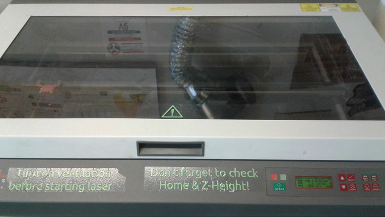
The laser cutter.
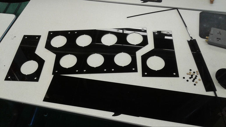
The bottom sheet.
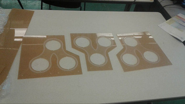
The top clear sheet, with the protective paper still on, to be removed during assembly.
With all parts fabricated, I had to assemble the controller body. I had two 12x15x3” boxes laying around, so I stitched them together with some long bolts to make a 12x30” box, which was just the right size for the acrylic sheets I had cut out. The acrylic was then assembled on top and loosely bolted into place after cutting out holes in the cardboard box. The buttons were then inserted and and tightened, along with the bolts.
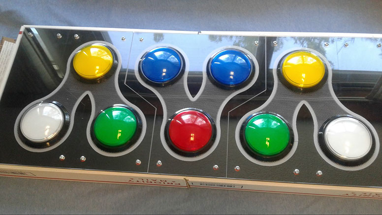
The final exterior look of the controller.
The hardware was in place, and now had to be wired. I strapped the Arduino down with a piece of cardboard to stop it from shifting around during gameplay, then proceeded to wire up the buttons using the crimp connectors and wire I bought previously at the ECE Supply Center. I daisy chained all the LED Highs to the 5V port, and also daisy chained all the microswitch grounds. Then, for each button, I connected LED Low, the microswitch NO terminal, and a convenient port on the Arduino.
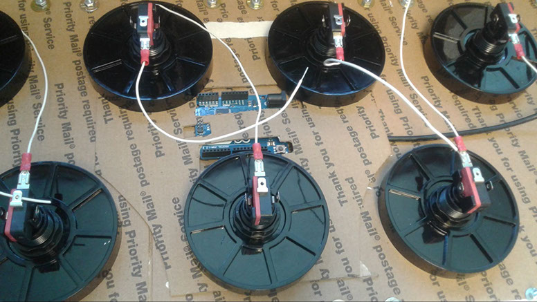
The strapped down Arduino.
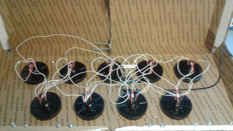
The completed wiring.
Next, I had to code the Arduino to act as a game controller. I picked up a few public libraries and example code, then modified it to fit.
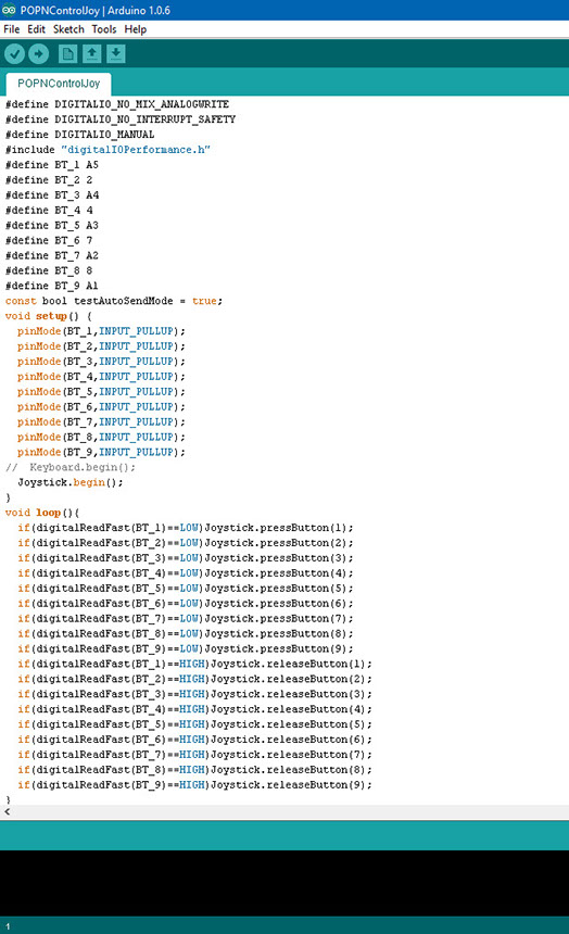
The Arduino code.
A quick test showed that all the buttons registered as gamepad inputs, and all the LEDs lit up whenever the buttons were pressed. A success!
